![]()
![]()
![]()
|
|
|
|
THEORY For practical application our goal was to construct the simplest, physically-based model that would capture the topographic effects described above. As shown below, we have been able to reduce the model to a point where it can be literally parameter free. The value of such a model is that: 1) it can be applied in diverse environments without costly attempts at parameterization - hence it is fully transportable, unlike empirical correlational approaches (see review in Montgomery and Dietrich, 1994); 2) results from different sites can be directly compared; 3) it takes little special training to use the model, and 4) it becomes an hypothesis that is rejectable, i.e. the model can fail - rather than just be tuned until it works. The value of a model that can fail is that it can effectively put a spotlight on processes not included in the model that are important. This means the model can help point a finger at causality.
Slope stability model SHALSTAB is based on an infinite slope form of the Mohr-Coulomb failure law in which the downslope component of the weight of the soil just at failure, t, is equal to the strength of resistance caused by cohesion (soil cohesion and/or root strength), C, and by frictional resistance due to the effective normal stress on the failure plane:
in which s is the normal stress, u is the pore pressure opposing the normal load and tanf is the angle of internal friction of the soil mass at the failure plane. This model assumes, therefore, that the resistance to movement along the sides and ends of the landslide are not significant. A further simplification in SHALSTAB is to set the cohesion to zero. This approximation is clearly incorrect in most applications. Although the rocky, sandy soils of colluvial mantled landscapes probably have minor soil cohesion, root strength, which can be treated as an additional cohesive term in (1), plays a major role in slope stability (e.g. , Burroughs and Thomas, 1977; Gray and Megahan, 1981; Sidle, 1992). We have elected to eliminate root strength in this model for several important reasons. First, root strength varies widely, both spatially and in time. Although field studies show that root strength is quantifiable (i.e. Endo and Tsuruta, 1969; Burroughs and Thomas, 1977; Gray and Megahan, 1981), to do so would involve considerable effort. For watershed scale modeling, parameterization of root strength patterns across the landscape would be very time consuming. It is conceivable that remote sensing of canopy types could be used to estimate possible root strength contributions, but such a method, requiring high spatial resolution information has not to the best of our knowledge been developed. Hence, we excluded this term in order to not have a free parameter. A second reason we excluded it is that we reasoned that this would be a very conservative thing to do. If we are concerned with forest practices and landslide hazard mapping, then setting cohesion to zero maximizes the extent of possible instability across the land. As discussed below, we have somewhat compensated for the absence of root strength by setting the friction angle to a high, but acceptable value. This is not to say that there is no value in building models with root strength, and several such models exist which employ digital elevation data (e.g., Dietrich et al., 1995; Wu and Sidle, 1995; Montgomery et al., 1998; in press). We now refer to a subsequent version of SHALSTAB in which the soil depth and cohesion are held spatially constant as SHALSTAB.C (used by Montgomery et al., 1998, in press). A version of SHALSTAB in which the soil depth varies spatially, the hydraulic conductivity varies vertically and the cohesion is spatially constant is now referred to as SHALSTAB.V (developed by Dietrich, et al., 1995). By eliminating cohesion, (1) can be written as
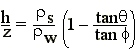
in which z is soil depth, h is water level above the failure plane, rs and rw are the soil and water bulk density, respectively, and g is gravitational acceleration (see Figure 4). This equation can then be solved for h/z which is the proportion of the soil column that is saturated at instability:
For some this simple equation may tell a surprising story. It explicitly states that the soil does not have to be saturated for failure! While this is nearly always assumed when one analyzes a landslide scar, theoretically it is not necessary. Note that h/z could vary from zero (when the slope is as steep as the friction angle) to rs/rw when the slope is flat (tanq = 0). An important assumption, however, will be used below which sets a limit on what h/z can be. We will assume that the failure plane and the shallow subsurface flow is parallel to hillslope, in which case h/z can only be less than or equal to 1.0 and any site requiring h/z greater than 1 is unconditionally stable - no storm can cause it to fail. Figure 5 illustrates the relationship between h/z and tanq for an angle of internal friction of 45° and a bulk density ratio of 1.6. Note that four distinct stability fields emerge. Any slope equal to or greater than the friction angle will cause the right hand side of (3) to go to zero, hence the site is unstable even if the site is dry (h/z = 0). We have called this "unconditionally unstable" and have found that it commonly corresponds to sites of bedrock outcrop. Because h/z cannot exceed 1.0 in this model, if tanq is less than or equal to tanf(1-(rs-rw)) then the slope is "unconditionally stable". We observe in the field that such environments can support saturation overland flow without failing. The two other stability states are "stable" and "unstable", with the former corresponding to the condition in which h/z is greater than or equal to that needed to cause instability (given by the right hand side of equation (3)) and the latter corresponding to the case in which h/z is less than that needed to cause instability. Figure 6 illustrates the spatial pattern of h/z needed for failure for the area near Coos Bay, Oregon shown in Figures 1 and 2b. Note that stable areas in Figure 6 are those which require h/z to exceed 1.0. We selected this site because we have been working in this area since 1988 and we have extraordinary topographic, hydrologic and erosional information about it. Later we will discuss the effects of grid size and topographic data quality on model performance. The pattern of h/z needed for instability at the Coos Bay site in Figure 6 simply reflects the local slope: the steeper the hillslope the smaller the amount of water needed for instability. For a given storm, the actual pattern of h/z due to subsurface flow across the landscape will differ greatly from that shown in Figure 6. Subsurface flow will spread away from the noses and ridges, keeping h/z relatively low there, whereas it will concentrate in the valleys, elevating h/z to the highest values. Local instability occurs when the topographically-driven shallow subsurface flow produces a saturation (i.e. h/z) that matches that shown in Figure 6. Hence this figure defines what is needed for instability, but a shallow subsurface flow model must now be used to predict the hydrologic response that might produce the appropriate h/z.
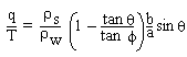
Hydrologic model To model the hydrologic controls on h/z, we use a steady state shallow subsurface flow based on the work by O'Loughlin (1986) and which has similarities to TOPOG (Beven and Kirkby, 1979) (although our model is much simpler). We assume that the steady state hydrologic response model mimics what the relative spatial pattern of wetness (h/z) would be during an intense natural storm which is not in steady state. This assumption would break down if precipitation events are sufficiently intense that thin soils on non-convergent sites can quickly reach destabilizing values of h/z before shallow subsurface flow can converge on unchanneled valleys. Efforts to model this effect do not show it to be likely (Hsu, 1994), but more work should be done on this problem. Figure 7 illustrates the geometry and routing of water off the landscape used in our hydrologic model. If we assume that there is no overland flow, no significant deep drainage, and no significant flow in the bedrock, then q, the effective precipitation (rainfall minus evapotranspiration) times the upslope drainage area, a, must be the amount of runoff that occurs through a particular grid cell of width b under steady state conditions. Using Darcy's law we can write that
in which sinq is the head gradient. At saturation the shallow subsurface flow will equal the transmissivity, T, (the vertical integral of the saturated conductivity) times the head gradient, sinq and the width of the outflow boundary, b and this we can approximate as follows:
Combining (4) and (5) leads to:
Here we see that the pattern of h/z for a given storm is determined by two things: a hydrologic ratio and a topographic ratio. The hydrologic ratio is q/T. This ratio captures the magnitude of the precipitation event, represented by q, relative to the subsurface ability to convey the water downslope, i.e. the transmissivity. The larger the q relative to T the more likely the ground is to saturate, and clearly the greater the number of sites on a hillslope that will become unstable (where the h/z specified by (6) exceeds that given by (3)). The topographic ratio, a/bsinq, captures the essential effects of topography on runoff. The effect of topographic convergence on concentrating runoff and elevating pore pressures is captured in the ratio a/b, which shows that the larger the drainage area relative to the cell width, the higher h/z. The steeper the slopes, the faster the subsurface flow and the consequently the lower the relative wetness defined by h/z. The topographic ratio is nearly identical to that identified by TOPMODEL (Beven and Kirkby, 1979) and is very widely used in local and regional hydrologic modeling. The important difference is that TOPMODEL uses tanq rather sinq. Physically, tanq is incorrect and while this mistake has no impact on low gradient systems, the error on hillslopes is significant if tanq is used instead of sinq.
Figure 8a shows the spatial pattern of a/(bsinq) for our study site near Coos Bay. This topographic ratio is clearly highest in the valleys and increases downslope as a/b increases and sinq decreases. Comparison with Figure 8b shows that the basic spatial structure of the topographic ratio is dominated by a/b, the convergence term. Note that on steep hillslopes sinq has a small range whereas a/b varies by orders of magnitude. Because sinq is less than 1.0, it elevates the value of the topographic ratio (hence increase h/z), with the greatest influence on the gentlest slopes. Hence, flat areas with modest drainage areas, such as roads, will have large h/z values compared to comparable drainage areas on steep hillslopes. Figure 9 shows the pattern of h/z as a function of different values of q/T based on equation (6). This map does not show the h/z needed for failure, rather it just shows the proportion of the soil column that would saturate for a given hydrologic event characterized by the relative magnitude of the effective precipitation and the soil transmissivity. Because q/T is always a small number, we typically report the logarithm of the value. Table 1 provides a conversion table from T/q to q/T to log (q/T). Each map varies by an increment of -0.3 of log(q/T) which is equivalent to a factor of 2. Hence if we assume that the transmissivity is the same in all the maps, then each map represents the effect of doubling the effective precipitation, q by a factor of two. The effective rainfall is 32 times higher in the last map (log (q/T) of -1.9 than in the first map (log (q/T) of -3.4). TABLE 1
The actual effective steady state rainfall can be calculated if the transmissivity is estimated. Based on detailed field work at our small study site near Coos Bay, we have estimated the transmissivity to be about 65 m2/day (Montgomery and Dietrich, 1994). Hence a value of log(q/T) of -3.4 means that the steady state rainfall was 26 mm/day, where as a value of -1.9 was 818 mm/day. While true steady state rainfall and runoff are not reached in real landscapes, daily rainfall of 26 mm occurs and storms can produce the hydrologic effect equivalent to this steady state rainfall response. The value of 818 mm/day is clearly unreasonable. Again, we emphasize that the assumption in this model is that the steady state hydrologic model mimics the effect of transient rainstorms whose short term effective rainfall is greater than the steady state value. As Dietrich et al. (1992,1993) and Montgomery and Dietrich (1994) have discussed, limits on the value of q or q/T can be placed based on the predicted pattern of saturation and its comparison with qualitative field observations. The idea is that this q/T sets a bound between commonly occurring hydrologic events that lead to maintenance of the channel network and rare events that can occasionally cause upslope erosion. For example, in Coos Bay, overland flow only occurs in the channel networks, hence q/T values that cause h/z to greatly exceed 1.0 in the steep unchanneled valleys would be unrealistic. Comparison with Figure 2b reveals that the current extent of the channel network is quite similar to the up valley extent of values of h/z > 1.0 for log (q/T) = <-3.4, and that by -2.5 many of the valleys which do not support a channel show saturation. One unexpected result of being able to use high resolution laser altimetry data is that the potential effect of road runoff on slope stability can become evident. The ridge line road network, which is partially visible in Figure 1, captures drainage area and diverts it into valleys. This is easily visible in Figure 9, even in the lowest rainfall rates. The drainage area effect is also visible in Figure 8b. While the calculated value of h/z may be misleading for the impermeable surface of the road tread, the hydrologic routing effect of captured drainage area is reasonable and is similar to the field results reported by Montgomery (1994).
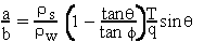
Coupled hydrologic and slope stability model: SHALSTAB Now we can combine the slope stability model (3) and the hydrologic model (6) and solve for either the hydrologic ratio:
or the area per outflow boundary length
Equation 7 is the coupled hydrologic-slope stability equation solved by SHALSTAB. The model has three topographic terms that are defined by the numerical surface used in the digital terrain model: drainage area, a, outflow boundary length, b, and hillslope angle, q. There are potentially four parameters that need to be assigned to apply this model: the soil bulk density, rs, the angle of internal friction, f, the soil transmissivity, T, and the effective precipitation, q. As we will discuss under the Application section, we have found it useful to assign bulk density and friction angle values to be the same everywhere, and compare q/T values, making (7) a parameter free model. Of course, if data on soil properties are available, then the locally appropriate values could be used (but other neglected parameters, i.e root strength may need to be considered). Although (7) can be reduced to a parameter free condition, it is still dimensional. The ratio of q/T is equal to length/time over length squared per time, i.e. it has the dimensions of 1/length. Throughout this report we will use the metric system, and the unit of q/T will be 1/meters or for T/q it is meters. Likewise, the dimension of a/b is meters. Figure 10 shows for our Coos Bay study site that the area predicted to be unstable progressively expands up the valleys and eventually across the slope as T/q lowers (or as log(q/T) increases), simulating the effect of progressively larger storms. We find that for a wide variety of sites and grid sizes, cells with values smaller than -2.5 to -2.8 for log(q/T) are largely confined to the unchanneled valleys, but for larger values (say -2.2) the instability spreads across the landscape onto planar hillslopes and ridges. To explore how the model works, we have plotted the value of log(q/T) for instability against slope (in degrees) for various values of a/b (setting f = 45° and bulk density ratio equal to 1.6) (Figure 11). It is perhaps surprising to discover here, that there is no dependency on slope up to 30 degrees, and from 30 to 40 degrees the decrease in log(q/T) is less than or only slightly greater than the log(q/T) class interval of -0.3 we use in our maps Hence, the spatial pattern of slope instability is almost totally dominated by the convergence term, a/b up to gradients of 40 degrees. To illustrate this point, we have plotted a map of log(q/T) values needed for instability for our Coos Bay site (Figure 12) in a matching color assignment for that used in the map of a/b in Figure 8b. This observation on the effect of a/b is consistent with the emphasis placed, based on extensive field work, on unchanneled valleys as sites of dominant slope instability. As the landscape becomes very steep (greater than 40 degrees) this local gradient dominates. (We note here that the version of SHALSTAB used by Montgomery et al. (1998) (here referred to as SHALSTAB.C) in which soil depth is assumed constant and equal to 1 m, friction angle is set at 33°, density ratio is 1.6 and root strength is 2 kPa, yields nearly identical results to that shown in Figure 12 up to about 35°. For steeper slopes, SHALSTAB.C predicts greater instability (i.e., lower log(q/T) than does the cohesionless model reported here! This is because the low root strength does not completely compensate for the low friction angle for steep slopes.) We have also found it illuminating to plot equation 7 on a graph with axes of a/b (contributing area per flow boundary length) and the tanq, the hillslope gradient (Figure 13). The appeal of such a graph is that the two topographic factors that can be readily obtained from a digital terrain model, a/b and tanq, form the axes and consequently every cell on the landscape can be plotted directly on this graph and compared with various runoff and erosion theories (see Dietrich et al., 1992, 1993; Montgomery and Dietrich, 1994b; and Prosser and Abernathy, 1996, for further discussion). In effect, we can consolidate the series of graphs shown in Figure 10 into a single plot. Equation 7b appears as a curve on this graph terminating where tanq = tanf and where tanq = tan f (1- rs/rw)). That sets the bounds on "unconditionally unstable" and "unconditionally unstable", respectively, just as before in figure 5. The position of the line separating "unstable" and "stable" fields depends on the hydrologic ratio. Note that if h/z is equal to 1.0 (i.e. saturation) then equation (6) can be written as a/b = (T/q ) sinq. The dashed line on figure 10 is a plot on this relationship. Any cell that falls above the line would be saturated and any that falls below the line would be unsaturated for the hydrologic event defined by the hydrologic ratio. Hence, the intersection of this line with the vertical line bounding the "unconditionally unstable" field determines the termination point of equation (7), as the lower bound of instability is the case of saturation. The combination of equations (6) and (7) in figure 11 leads to the following stability fields TABLE 2.
Figure 14 illustrates the relationship between topographic form and stability fields for various T/q values in three watersheds along the Pacific Coast Range, one of which- Mettman Ridge- is a subbasin of the area shown in Figure 10 (but the analyses were performed on much coarser scale data). In these examples which were developed using TOPOG, convergent and divergent elements (located in valleys and noses, respectively) were defined using the shape of the elements. Most users will employ a grid-based method in which all elements are square shape. Instead of element shape, local planform curvature may serve as an adequate estimate of topographic setting. Plots of the kind shown in Figure 14 can be used to guide selection and interpretation of a T/q value to assign to a study area. Pack and Tarboton (1997) used such a graph to plot the values of landslide sites to show that the data conformed to the model.
Final comments on the theory SHALSTAB is equation 7. It can be used with field data to assess similarity and differences in landslide locations. In order to use it in a digital terrain model, local slope and drainage area to a cell needs to be calculated. There are many ways to do this and we will describe the methods we employ next. We divide the problem of using SHALSTAB into three parts: the application, testing and prescriptive use of the model .
|
|
Copyright 1998, William Dietrich and David Montgomery
|